
We review their content and use your feedback to keep the quality high. We will need to discuss an Example to understand this in more details.

3 Bit Multiplier
Tation of the truth table with standard gates is also straigh tforw ard as giv en in Fig.

. 4-BIT BINARY FULL ADDER WITH FAST CARRY The SN5474LS83A is a high-speed 4-Bit binary Full Adder with internal carry lookahead. Sketch the gate level design of the circuit based on the Boolean equations you obtained. Deco der for the 4.
What is the Binary Adjuster. Consider the second last row of the truth table here the operands are 1 1 0 ie A B Cin. Here an extra gate is added in the circuitry OR gate.
Through this article on Adders learn about the full adder half adder Binary Parallel Adders Carry Look Ahead Adder BCD Adder Serial Adder with circuit diagrams and truth tables. The Boolean Expression describing the. It accepts two 4-bit binary words A1A4 B1B4 and a.
You are unlikely to find full truth table of a 4-bit adder circuit. Details below with circuit and a truth-table. A digital binary scale is a digital device that adds two binary numbers and gives its sum in binary format.
4-BIT BINARY FULL ADDER WITH FAST CARRY The SN5474LS283 is a high-speed 4-Bit Binary Full Adder with internal carry lookahead. Using Shannons expansion theorem expand both Cout. Or VIL per Truth Table VOL Output LOW Voltage 54 74 025 04 V IOL 40 mA VCC VCC MIN Output LOW Voltage VIN VIL or VIH 74 035 05 V IOL 80 mA.
A combinational circuit can hold an n number of inputs and m number of outputs. We will use a full adder logic chip and add 4 bit binary numbers using it. The two numbers to be added are known as Augand.
SoC Design LabSoC Design Lab. So to design a 4-bit adder circuit we start by designing the 1 bit full adder then connecting the four 1-bit full adders to get the 4-bit adder as shown in the diagram above. In this example we will use some terms from Register Transfer Level RTL implementations.
See the answer See the answer done loading. Circuit of 4 Bit Binary Adder consisits of a sequence of full-adders. 4-bit Ripple Carry Adder carries out the addition as explained in the following stages- Stage-01.
Add two binary numbers 7 and 15 with previous carry. But I must warn you it is going to be large because there are so many combinations of input a 4-bit adder can have. A1 A0 C3 CC C21 0 Figure 10.
Answer 1 of 3. These numbers are to be added using a 4-bit ripple carry adder. The Sum out Sout of a full adder is the XOR of input operand bits A B and the Carry in Cin bit.
It accepts two 4-bit binary words A1A4 B1B4 and a. ContentsContents Implementation of Half-Adder Implementation of Full-Adder Implementation of 4-Bit Adder-Subtractor 2. Understand more about RTL.
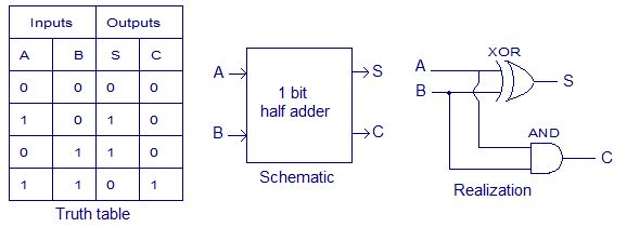
Simply a circuit in which different types of logic gates are combined. In previous half-adder tutorial we had seen the truth table of two logic gates which has two input options XOR and AND gates. Get the 4-bit full adder truth table and design the logic circuit with gate.
When C in is fed as input to the full Adder A it activates the full adder A. If you need it very much you have to generate it. Experts are tested by Chegg as specialists in their subject area.
Draw the truth table ABCin000111 of a one-bit full adder. Truth table and schematic of a 1 bit Full adder is shown below. Then at full adder A A 0 1 B 0 0 C in 0.
Hanbat Hanbat National National University University 4-Bit Adder-Subtractor4-Bit Adder-Subtractor Gookyi Dennis A. 4 bit ripple carry full adder truth table. Full Adder Truth Table - 17 images - lec20 half adder full adder truth table logic circuit combinational circuit adder circuits notesformsc full subtractor.
We will use TTL 4 bit binary adder. Full adder A computes the sum bit and carry bit as. Expansion of 1-bit full adder to mak e a 4-bit adder.
There is a simple trick to find results of a full adder. Per Truth Table VOL Output LOW Voltage 54 74 025 04 V IOL 40 mA VCC VCC MIN Output LOW Voltage VIN VIL or VIH 74 035 05 V IOL 80 mA V or V. Based on truth table draw the Karnaugh maps for Cout and Sum separately find the simplified Boolean equations for Cout and Sum.
For the 1-bit full adder the design begins by drawing the Truth Table for the three input and the corresponding output SUM and CARRY. You can learn more about Logic gates here. CircuitVerse supports multi-bit-wires which means that the circuit design is easier faster and not included.
Who are the experts. For generating truth table you have to. 243 Making a Multiplier from an Adder In class w e will discuss ho w to use our full adder the c hip to mak ea m ultipli er.

Binary Multiplier Types Binary Multiplication Calculator

Verilog Code For Pipelined Mips Processor Coding Processor Math
One Way We Could Expand The Capabilities Of Either Of These Two Counter Circuits Is To Regard The Q Outputs As Another Set Of Four B Counter Expand Binary

Carry Save Adder Vhdl Code

Moore State Machine Vhdl Code Coding Detector States

Vhdl Code For Full Adder

Vhdl Code For 2 To 4 Decoder

Pin On Electronic Circuit Design
Difference Between

Vhdl Code For 4 To 2 Encoder

Verilog Code For 16 Bit Single Cycle Mips Processor

Binary Adder Subtractor Construction Types Applications

Design 4 Bit Voting Combinational Eircuit That Has Two Outputs One Output To Indicate Mejority And Snother To Indicate A Tie Vot Homework Help Equations Logic

Experiment Write Vhdl Code For Realize All Logic Gates

Vhdl Code For Full Adder

4 Bit Ripple Carry Adder Vhdl Code

Pin Page

Binary Multiplier Types Binary Multiplication Calculator

Binary Multiplier Types Binary Multiplication Calculator


